Ten Minute Master – Studio Connectivity
Linking up equipment in the studio, whether that be a project room or a larger installation, can be daunting. Russ Hepworth-Sawyer explores the ins and outs… Despite the dominance of digital audio these days, there will be times when we still need to move analogue audio about using some form of cable or another – […]
Linking up equipment in the studio, whether that be a project room or a larger installation, can be daunting. Russ Hepworth-Sawyer explores the ins and outs…

Despite the dominance of digital audio these days, there will be times when we still need to move analogue audio about using some form of cable or another – a mic signal in need of preamplification, for example, or a mix signal having a buss compressor applied to it. Firming up your knowledge of connectivity will be invaluable as you set up, alter or simply improve signal flow, and there will always be sessions that require some ‘higher thinking’ as you connect legacy real instruments to your setup.
Balancing Act
Between each connection is a cable – and not every cable is the same. Audio signals, especially microphone signals, are extremely quiet and can introduce noise such as electromagnetic interference from signals nearby. If you play electric guitar you’ll almost certainly identify with noise that can be inducted by the guitar cable. Decent cables have a shielding material that is a bit like aluminium foil, or braided wire wrapped around the cores of the cable. Shielding ‘soaks up’ inducted interference by sending it to ground long before it’s conducted to the positive cable.

Shielding alone sometimes isn’t enough to deal with heavy mains spikes. To prevent these becoming a problem an extra positive signal is conveyed, but this one is out-of-phase with the original. The ‘balanced’ theory is that any noise inducted on the positive cables will be in phase, but the desired audio signal is out-of-phase. The receiving device brings the two positive signals back into phase with each other, leaving the noise inducted on the cable out-of-phase with itself and thus eradicated.
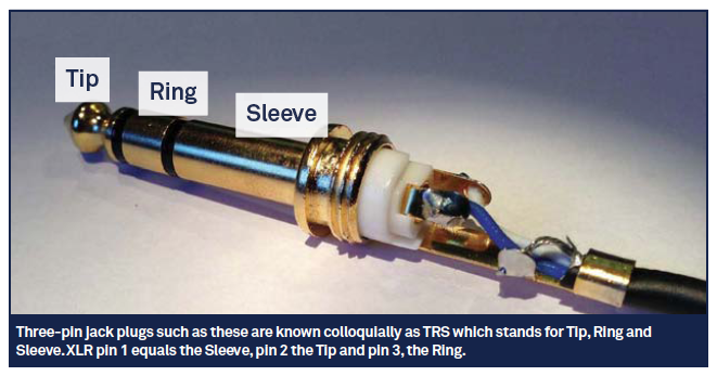
XLR connectors have three pins connecting a ground and the two out-of-phase positives. These three connections make up the balanced signal and can be connected to, say, a GPO B-Gauge (aka 316) or a 1/4-inch jack plug (often referred to as TRS – Tip, Ring, Sleeve, describing the contacts on the plug).
GPO B-Gauge (316) plugs are commonplace, particularly in broadcasting. The format has its history in UK telephone switchboards at a time when operators would connect calls for you physically using a patch cable. They format can handle higher voltages such as phantom power, making them a good choice for microphone patchbays.
TRS jack plugs are a variation on the 316 design. Instead of the round head of the 316 the 1/4-inch jack has a diamond-shaped tip. Inserting a TRS into a 316 patchbay can cause upset, as the TRS diamond tip is somewhat wider than the 316’s dome. This can mean the patchbay’s connectors are bent a little too far to properly connect with a subsequently inserted 316.

Patch Perfect
Many studios now opt for bantam patchbays. Despite the increased cost, these take up less space as 96 sockets can fit within 1U of rack space (TRS is typically 48 sockets across two rows of 24 per 1U of rack space). The rear of bantam patchbays, just like many consoles/control surfaces such as the C|24, use the D-Sub 25 connection protocol, permitting eight balanced channels of audio per cable.
Other multi-pin connection formats are also in use. EDAC is one example, once employed on the original ADATs but still used to connect some bantam patchbays to desks. These and multi-pin connectors are largely found in live audio applications, permitting quick dismantling at the end of a night without requiring you to reconnect every jack to the mixer.

Making Connections
At times you’ll need to connect a balanced signal to an unbalanced input or vice versa. Connecting a line-level signal (ie a portable recording device or synth) to a balanced input is perfectly fine. The relative level might be a little lower, but they’ll be able to ‘understand’ each other just fine. An example of this kind of setup might be an RCA phono connection you’d like to connect to balanced inputs for tracking. In this eventuality you’ll need a phono-to-mono (2-pole) jack (with only a sleeve and tip) unless it’s a domestic turntable, which will require specific preamplification.
To connect phono-equipped equipment to XLR equipment you’ll need to ensure that the phono’s positive and negative are connected correctly to all three pins of the XLR. In essence, the positive continues to go to pin 2; pins 1 and 3 are connected to the negative of the phono plug. The out-of-phase positive signal is thus sent to ground and discarded.

Balanced cabling is an ingenious solution to overcoming inducted noise by turning the interference out-of-phase with itself.
Converters exist that permit all manners of connections, from the simple phono-to-jack to the more complicated gender-changing types that permit two male XLR plugs to be connected together. Obtaining a selection of these is worthwhile as they are useful to have in the studio for those ‘what if’ sessions.
Acknowledging whether a signal is unbalanced or balanced is one thing, but to appreciate its impedance is another. We’re fortunate in audio that impedance is not a daily worry as much of the matching is taken care of for us. We’re concerned with matching the voltage. Typically, gear has high-impedance inputs that permit all manner of low-impedance outputs to be connected to it. However, the Hi-Z inputs on some devices permit for instruments to be connected straight in without impedance matching.
Without these inputs, an impedance-matching device is required – a DI box (Direct Inject). The mic input on a console is a low-impedance input (around 1,200 or 2,400 ohms) whereas an electric guitar could be around 100K ohms. A DI box employs a transformer to allow the mic input to accept the higher impedance of the electric guitar. Failure to match these affects the tonality of the instrument as the signal is altered – distorted, if you will.
Many connections noted here are mirrored for digital audio connectivity. For example, AES/EBU employs XLR, whereas S/PDIF uses phono. Developments now mean that networked audio connectivity such as RedNet from Focusrite may become the norm, running on Cat5 cabling. Nevertheless, many of ‘us’ will continue to use traditional, treasured and time-tested analogue microphones, mixers and monitor controllers – for ‘us’, the above will remain of relevance for years to come.
Further Info
To understand the types of connectors used in audio, go to: www.vdctrading.com
For a glimpse of potential future studio connectivity, visit: http://uk.focusrite.com/rednet