Max MSP Beginners Guide: Creating a filter for a software synthesizer
Learn how to build a filter system to attach to the oscillator to shape your sound

Creating a filter for a software synthesizer
If you haven’t caught up on the previous three tutorials where we go through the basic tools needed to use Max MSP, how to build an input/output and oscillator, and how to build an envelope system, please do so before following this tutorial.
In this guide, you’ll learn how to create and insert a filter system into your synthesizer to ‘cut off’ certain frequencies to tame your sound.
The first step is to open up your patch from the last tutorial and ensure that the page is set up correctly before we start patching as unfortunately these do not save, and need to be reset each time you open up Max MSP. You can refer back to Part 1 of this tutorial series if you need any guidance.
Next, create a new sub header on your patch and name it Filter. Due to its function, it is best placed to the right of the Oscillator.
The Filter
Max MSP provides plenty of filter choices and options, but to continue with the ethos of finding simple multi-purpose objects to help us build the monophonic software synthesiser, we’re going to use the object ‘svf~’.
This handy object allows you to choose between a low-pass filter, a high-pass filter, a band-pass filter, and a notch filter. So, all you have to build is a means of selecting between the four options, plus a controller for the cut-off frequency.
Before we move onto the selection system, which will be a lot simpler to set up than the envelope pre-sets, you’ll want to create a slider to control the filter’s cutoff frequency. This isn’t a gain slider like we’ve used in the past, but the object called ‘slider’.
This object allows you to set the slider to move between values, rather than just scaling signals.
Once you’ve created the object, you need to connect it to the middle inlet of ‘svf~’, named Cutoff Frequency. The values for the slider now need to be set.
Highlight the object, and open up the inspector on the right-hand side of the patch. If you scroll down to the bottom, you can set your range to a desired frequency, (we’ve set it to 1,000 Hz). The output minimum should be 0, and the output multiplier should be 1.
Selection system
The filter object and cutoff frequency object have been placed in the patch, but now you’ll need to find a way to select the individual filters so they can eventually be connected to the rest of the synthesizer.
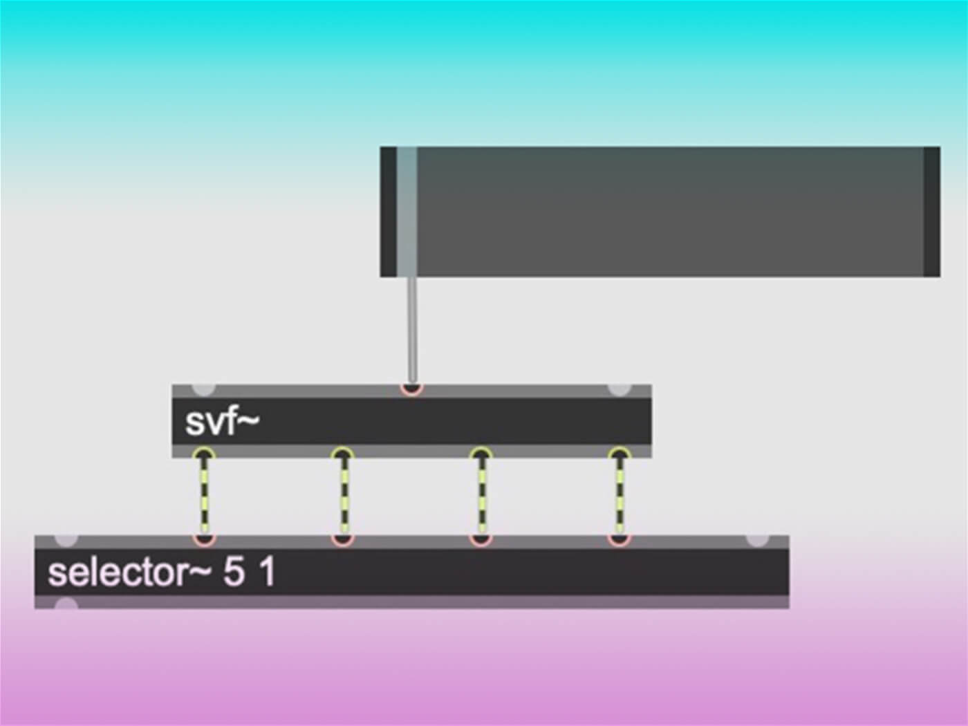
Firstly, you’ll need the object ‘selector~’. If you open up the help file for the object, you can see that we need to tell the object how many inlets and outlets it needs to create. As we have four different filters, plus the dry unfiltered signal, we need five inlets, and only one output.
The four filters need to wire into the first four inputs (not inlets) of the ‘selector~’ object, leaving the fifth empty for the dry signal. If you get confused about what each inlet does, you can hover over it with your mouse, and it will tell you. Therefore, the object should look like this:
Instead of using messages and bangs to tell the selector what to do, we’re going to use a ‘radiogroup’. We need to establish a way to pick between the five options, so this provides a list of choices that will send our selector a number that will tell which input to ‘open’ and ‘close’.
After you have put the object ‘radiogroup’ into the patch, open up the inspector window on the right-hand side of the patching window. Scroll down to where it says ‘number of items’ and replace the number ‘2’, with the number ‘5’. This is because we want to have five options: the four filters and the dry signal.
Next, you need to connect your ‘radiogroup’ to the first inlet of the ‘selector~’. However, because you want to see what number the radiogroup is sending to the selector, you need to add a ‘number’ object in between. If you hover over the inlets on the selector, it should also tell you what is open and what is closed.
When tinkering around with the radiogroup, you might see that it isn’t sending the selector ‘1-5’, but instead ‘0-4’. This means that it’s not lining up with the five filter options we want, and won’t work for your synthesiser.
There’s a simple fix for this. As we want our radiogroup to choose between the five inputs on the selector rather than just the first five inlets on the ‘selector~’ object, we need to tell it to add one on to every number, making it read 1-5.
To do so, add another object named ‘+1’ below the radiogroup, but above the number. Once this is done, it will only select the five inputs that are connected to the filter options. Don’t worry that the fifth input is empty – this will be connected to the oscillator in the next section.
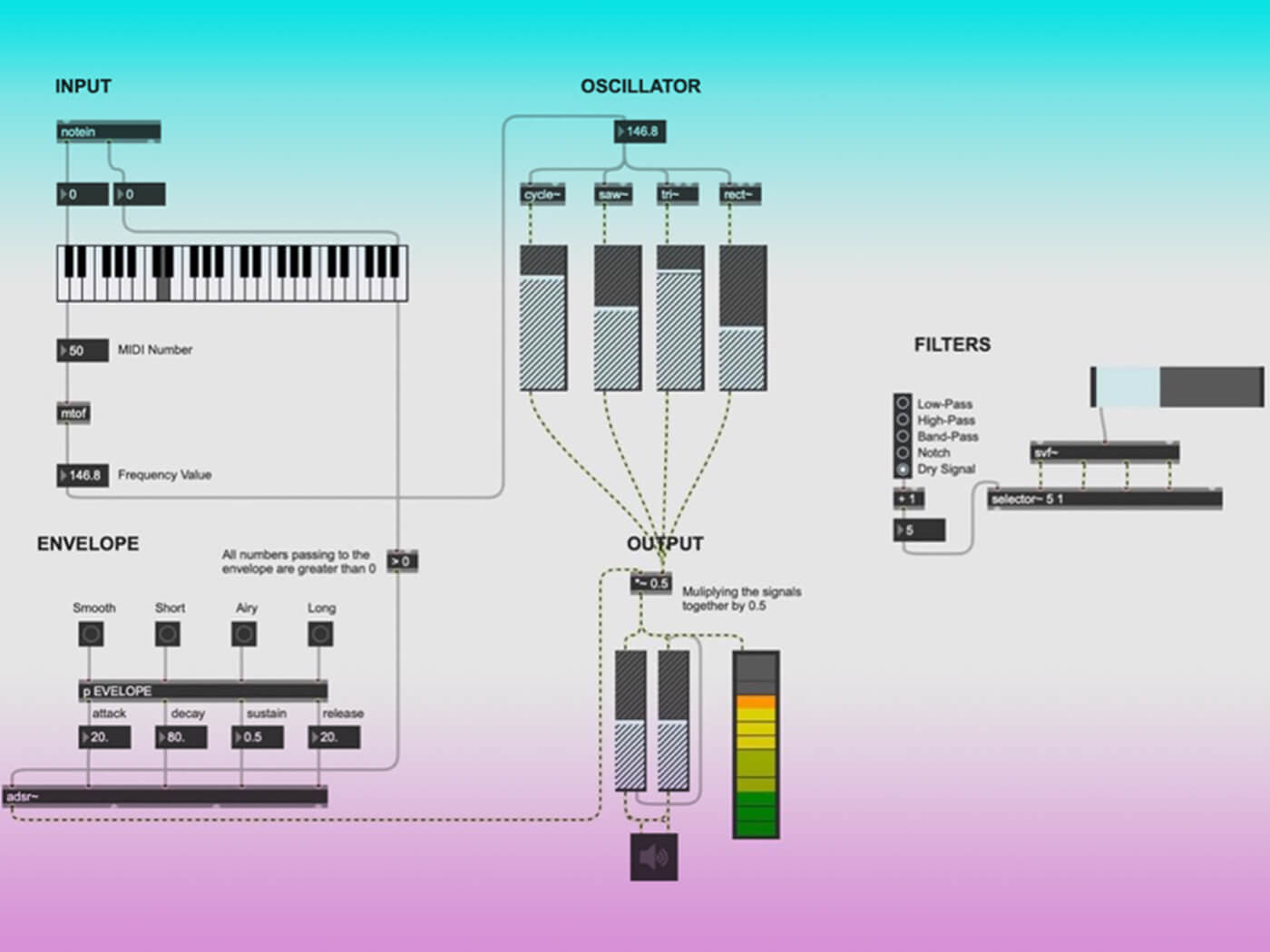
At this point, your patch should look like this:
Connecting the Filter to the patch
You now need to hook the filter object to the oscillator, and to the output.
Due to the nature of the filter object and how it will manipulate the sound generated by the oscillator, the oscillator no longer needs to be connected to the output, but instead to the filter.
You need to send the oscillator not only to the filter object but also to the selection object – you’ll want the raw signal to be a filter option. Connecting the filter to both objects would require eight wires, so you’ll use send and receive functions to reduce the clutter on the patch.
These send and receive objects act as a routing system but without the need for wires. They’re most effective when you need to send a signal to multiple places.
To create a send object, type in the letter ‘s’ followed by what you want to name the signal route. In this case, it’s called ‘s Osc’ as the signal is being sent from the Oscillator. This needs to be attached to the outlets of the Oscillator.
Next, you need to make a receive object by creating an object and typing in the letter ‘r’ followed by the exact same signal route name. So, it should be ‘r Osc’. This will be attached to the input inlet of ‘svf~’. A second ‘r Osc’ object needs to be created and attached to Input 5 on ‘selector~.
Now the oscillator is connected to the filter, a wire from the outlet of the ‘selector~’ needs to be connected to the right inlet of the signal multiplier in the output. All five of the filter options have been wired correctly and should be triggered when selecting the right button on the radiogroup.
If you want to see what the filter and the cutoff frequency controller are doing to your signal, you can connect a ‘spectroscope~’ to the outlet of ‘selector~’.
You’ve now built your own software synthesiser! There is one more step to go as we turn it into something that actually looks like a synthesizer, and add the all-important presets, but the hard work is now over. Go and enjoy the fruits of your labour and feel free to tinker with all of the components until you find something you’re happy with.
If you haven’t yet downloaded Max MSP, Cycling 74 is offering a four-week free trial.